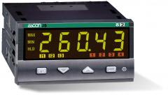
Indicator and transmitter with strain gauge Input
- Panel mount indicator 96 x 48 mm
- 1 high level or strain gauge input
- 1 Auxiliary high level input (optional)
- 1 retransmission output (optional)
- Automatic calibration routine
- Tare function for load cells
- Display of IN1, IN or CIN inclusive of
value, peak and valley and hold value
- RS 485 port with ModBus RTU Protocols (optional)
- 1 display, 5 digits, h: 15.5 mm,
configurable green or red colour
Process inputs:
1 Main Input IN1
- Voltage (V): 0/1...5 V, 0...10V
- Voltage (mV): 0/10...50 mV
- Current (mA): 0/4...20 mA
- Strain gauge: 350 Ω, with bridge excitation voltage: 5 V or 10 V
Accuracy : 0.25% ±1 digit (probes) or 0.1% ±1 digit (mA or mV)
Auxiliary input IN2 (Optional)
- Voltage (V): 0/1...5 V, 0...10V
- Current (mA): 0/4...20 mA
Accuracy : 0.1% ±1 digit: between 85...240 Vac the error is negligible
Resolution: 16 Bit
3 digital inputs
- NPN
- TTL
- Free Voltage
Keyboard
Mechanical:
3 multifunction keys + 1 dedicated for alarm acknowledge
Process outputs
1 High level analogue output:
- Current (mA): 0/4...20 mA
Up to 4 Optional outputs:
OUT1
- RELAY SPDT, 2A/250Vac
OUT2
- RELAY SPST-NO, 2A (250VAC)
OUT3
- RELAY SPST-NO, 2A (250VAC)
OUT4
- RELAY SPST-NO, 2A (250VAC)
Power supply:
- 24VDC/VAC
- 100… 240 Vac (50/60 Hz)
Transmitter power supply: 24 Vdc ±20%, 30 mA Max
Functions
Calculated value (CIN) Selectable between
- IN1 or IN2
- IN1 + IN2
- IN1 – IN2
- IN1 * IN2
- IN1/IN2
- (IN1 + IN2)/2 (average)
- MAX (IN1, IN2) (maximum value)
- Min (IN1, IN2) (minimum value)
Display indication of :
- Main input IN1
- Auxiliary input IN2
- Calculated Value CIN
- Peak and Valley indication
- Hold and temporized indication
- Automatic calibration routine
- Tare function for load cells
Alarms
- Up to 4 configurable alarms
- ISA-A Acknowledge function
Communication and programming:
Interfaces
- RS 485 port with ModBus RTU and J-bus (slave) protocols (optional)
Programming/configuration tools:
- Code selection
- Easy to use front interface for configuration
- Configuration software available for PC
Installation
Mounting method: panel mount
Case dimensions: 96 x 48 mm, depth 110 mm (1/8 DIN)
Connections
Signals connection
36 poles 5.5 mm² screw terminals block
Protection factor : IP 65 front protection
Display and indicators
1 display, 5 digits, h: 15.5 mm, configurable green or red colour
4 Alarm and 3 DI LED indicators
Connectable to:
- Any controller from Ascon Tecnologic range with the appropriate I/Os
- SCADA for monitoring, traceability and remote management
- DX and DY gateways for remote monitoring

File no. E176452
Ref. UL 504