Application
Technical features
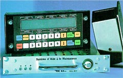
THE INTERFACE DRIVER/SYSTEM CONSOLE :
front face dimensions : 230 x 100 x 5 mm
box dimensions : 185 x 90 x 80 mm
It is the dialog tool between the driver and the on-board various equipments and, among them, the maintenance aiding system. Linked to the equipments of the system itself by a RS485 link with 4800 bauds transmission bus.
The console is the master equipment, it questions the other equipments considered as "slaves". Each slave equipment is able to control the display, the keyboard, the light and the buzzer of the console, under its control.
The console, embeddable in the vehicle\'s dashboard, is made of :
* a front face equipped with a LCD retrolighted display of 2 lines of 20 tactile keys, of the 1/4 turn locking system and a supple serigraphic keyboard.
* a back box receiving the electronic cards (mother card, CPU card, power supply card, optional card with 8 digital inputs/outputs.
THE TECHNICAL BOX :
dimensions : 270 x 260 x 44 mm
It records the information delivered by the sensors which are linked to it, such as the defaults declared by the driver on the interface console. The information is then delivered to the ground equipment through the infrared transceiver and to a maintenance portable PC that provides also the box programming.
It is a metallic box guided between 2 "U" racks mounted in the vehicle and it is made of :
* on the front face : 3 signalisation diodes (sensors, power supply, I/O) and a five pin connector for the PC plugging,
* at the back : 2 thirty-pin connectors (one for 24V power supply, transmission bus, vehicle's identification, and one for the 12 digital sensors and 2 impulse sensors, the travellers' counting and the infrared transceiver plugging).
the electrical components are grouped together on a mother card with a 80C31 microcontroller.
Junctions :
* RS232C for the portable PC,
* RS485 for the transmission bus,
* 5 points (I/O, +, - / earth) for the infrared transceiver.
THE INFRARED TRANSCEIVERS:
dimensions : 130 x 45 x 60 mm
The infrared transceivers permit the wireless communication between the vehicle and the ground. The infrared transceivers used in the vehicle and on the ground are the same. Infrared transceivers mounted in the vehicle are placed near the side window. The ground infrared transceiver is mounted on a portico on the roadside. the infrared transceiver is a plastic box with an optical window at 45° and includes a CMS mother card, an infrared I/O head and a five pin connector.
The operation voltage is from 18 to 32 V. Protection against polarity reversals and industrial and HF interferences. Serial link by current loop with bidirectional half-duplex transmission - Data format is transparent and the transfert speed is 9600 bauds.
THE GROUND INTERFACE:
dimensions : 600 x 600 x 400 mm
It establishes a link between the ground infrared transceivers and the central data processing system. Each circulation track is equipped with several transceivers permitting a data transmission at low speed. The infrared transceivers of each track are linked together with connection boxes. The data transmission cabinet is equipped with a rack receiving :
* 1 to 7 track cards,
* 1 PC ensuring the management of the track cards, the data storage, the link with the central data processing unit and the link with a portable PC,
* 1 power supply for the various cards and the ground infrared transceivers.
Junctions :
* 1 to 7 junctions 5 points for the link with the connection boxes,
* 1 RS232C for the link with the portable PC,
* 1 RS422 for the link with the central data processing unit.

